


Making fuel cells more efficient
15 March 2022
While fuel cells are seen by many as the cornerstone technology in any future hydrogen economy, there are still any number of questions concerning the technology and its ability to operate in real-world scenarios.
As with battery electric powertrains, operating range is a critical aspect in any mobile fuel cell system. It is estimated that fuel cell commercial vehicles will need, depending on the size and vehicle type, 200 to 600 miles of range to compete effectively with conventional diesel or gasoline-powered trucks and buses.
Already capable of delivering efficiencies of 40% to 50%, most fuel cells systems are well ahead of combustion engines. By comparison, gas and diesel engines running in generator sets at a steady state, deliver about 20% to 35% fuel efficiency.
PEM fundamentals
A fuel cell converts chemical energy of fuel, usually hydrogen, directly into electrical energy. It functions on the same principle as a battery, except the reactants and products are continuously added and removed from the system, and with this respect it functions similarly to an internal combustion engine. Power is generated in a fuel cell stack, which is the equivalent of the cylinder block of an engine. In both cases the efficiency of the energy generation process depends to a large extent on the balance of plant, those accessories that provide necessary services power to the fuel cell stack or engine.
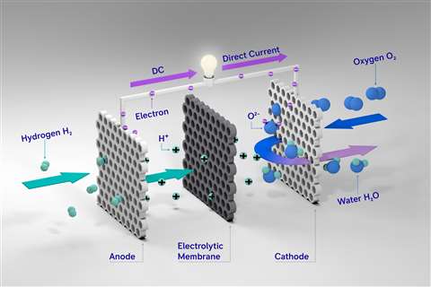 A rendering of the layout and functioning of a proton exchange membrane (PEM) fuel cell.
In the fuel cell stack, the fuel and oxidant, usually air, are separated by a proton exchange membrane (PEM), a center part of which is a solid electrolyte conducting hydrogen ions, while being non-conductive to electrons. The PEM consists of several layers. The electrodes are made of electrons-conducting materials (carbon and ionomer) with embedded particles of catalyst, usually platinum. Hydrogen molecules are split into ions (H+) and electrons (e-) in the presence of catalyst, with the reaction on the anode side of PEM. Ions are conducted through the solid electrolyte, while electrons are carried through external circuit as an electrical current.
Electrons return to the cathode side of PEM, where they combine with oxygen and hydrogen ions (H+) to create a water molecule.
Typically, a fuel cell stack is built with a number of cells in series in order to increase the resultant output voltage. PEMs are weakly permeable to gases like hydrogen, oxygen, nitrogen, water vapor and other impurities in the fuel. These impurities tend to accumulate on the anode and have to be removed in order to maintain high concentration of H2 on the anode.
Side effects
In fuel cell stacks, it is necessary to address unfavorable “side effects” of the energy creation process – and possibly improve the process – by creating more favorable conditions of fluids at the stack inlets. Both H2 and air pass narrow channels carved in the plates on both sides of the membrane. A side effect can be water droplet formation in the 0.5 x 0.5 mm (or smaller) channels, which block access of fuel to the reaction sites causing damage to the membrane electrode assembly (MEA).
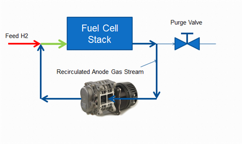 The anode loop of a fuel cell, with an Ogura TX blower used for hydrogen recirculation, along with water separation and purge systems. (Photo: Ogura)
These water droplets can be removed by increasing the H2 flow through the cell channels. This can be done by creating a pressure differential between the cell inlet and outlet, forcing the H2 to flow through the channels and pushing the water droplets to areas from which water can be drained.
This effect, called “hydrogen recirculation” is realized by using a mechanical device capable of moving wet hydrogen around the stack. The pressure differential should be less than 30 mbar, preferably in the range of 100 to 250 mbar. The presence of N2 and H2O in anode channels also decreases the H2 concentration, which negatively affects the reaction rates, but the higher density of these gases compared to H2 increases the efficiency of mechanical recirculation devices.
Apart from water droplet removal there are two other two positive effects of hydrogen recirculation:
- It increases the H2 concentration at the reaction sites.
- It provides the humidification of inlet H2 through mixing dry feed H2 with the recirculated wet H2, which enhances the reaction rates.
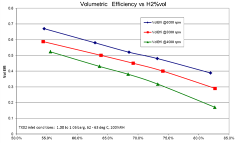 A chart indicating the volumetric efficiency of a hydrogen recirculation system using an Ogura TX blower. (Photo: Ogura)
The effect of increased humidification can be measured directly with a relative humidity (RH) meter. However the increased H2 concentration corresponds to the H2 recirculation rates provided by the H2 recirculation blower, which is not possible to measure directly in a real operating powerplant. A method to quantify the effectiveness of H2 recirculation devices would allow selection of the best designs and to establish the best operating conditions of these devices.
Balance of plant
To get the highest efficiencies from hydrogen, PEM fuel cells utilize electric motor-driven pumps, sensors and controls to maintain the proper hydrogen concentration at reaction sites to generate electricity. Just as overall engine efficiency is reduced by the presence of belt- and gear-driven accessories – alternators, fuel and water pumps, etc. – all of the needed balance of plant is a parasitic load on the fuel cell. And again, like an engine, the more efficient the balance of plant, the further the range from a fuel cell in an electric vehicle.
 A side effect of fuel cell operation can be the formation of water droplets in the channels of the membrane plates, which can lead to damage of the membrane electrode assembly. (Photo: Ogura)
Today, large fuel cell systems over 100 kW from Ballard Power Systems and other manufacturers incorporate Ogura Wankel-type positive displacement blowers to recirculate H2 and keep the PEM fuel cell operating at peak efficiency regardless of speed loads. Electric motors and their controllers are approaching efficiencies exceeding 90%, but H2 pumps are not as easy to measure due to the presence of the varied gases in anode loop – H2, N2 and water vapor – required to make the machine operate.
The following helps to explain how pump efficiency gains might be measured and tested on the fly.
In most cases, some type of hydrogen recirculation device (HRD) is used, and it has to be able to provide adequate anode gas recirculation. The ability to move water droplets out of cell channels through maximizing the anode inlet-outlet differential pressure (dP) is a crucial factor related to durability of the fuel cell stack, however, the dP measurement alone doesn’t provide enough information about the H2 recirculation rate, which corresponds to the increased H2 concentration resulting in the increased H2 chemical reaction rates, or in other words creating more power from the cubic inch of fuel cell stack.
In fuel cells, as in internal combustion engines, some excess air is provided for reaction rate improvement. In the fuel supply system, contrary to engines, it is possible to provide excess fuel, which also increases the chemical reaction rates. The excess fuel corresponds to the H2 recirculation rate.
Typically, the fuel cell stack manufacturer provides the requirement of this parameter, which known as “H2 Stoichiometry,” which is defined as a ratio of H2 flow in the stack inlet to the amount of H2 consumed in the stack. The unconsumed H2, along with the ballast gases, are moved from the stack outlet to the stack inlet through the H2 recirculation device.
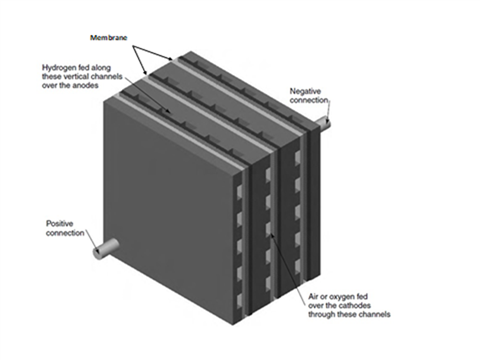 A depiction of a hydrogen fuel cell stack, showing the path of air and hydrogen through the membrane. (Photo: Ogura)
The challenge is to determine which part of the recirculated gas mixture is hydrogen. The stack supplier can specify the required H2 excess when testing stacks on dedicated test stations where the excess hydrogen is released from the stack outlet. In this situation there is practically no N2 present and the humidity of feed H2 can be set through the test station controls. In field applications, the N2 gas accumulates in the anode space when a mechanical device is used to move the hydrogen from the outlet to the inlet in a closed loop and its concentration (N2% volume) can be measured along with the RH percentage at the stack inlet.
Quest for efficiency
The more efficiency a fuel cell has, the greater the electrical energy output versus the hydrogen gas input. Proper chemistry is required to make a fuel cell work, but for larger PEM devices, hydrogen recirculation is a clear path to make them more efficient and provide significantly longer rage in mobile applications. A brushless dc electric (BLDC) motor-driven hydrogen recirculation system can pay for itself with the more efficient use of the fuel gases.
The Wankel Roots-style blower has proven to be well suited for this task. The minute airgaps (under 10ths of a millimeter) inherent in the Wankel rotor and casing design, when pumping water (or steam) as well as the fuel, have provided efficiency hitherto unavailable.
Moving hydrogen within a fuel cell is no small task and doing it efficiently is the Holy Grail of today’s larger fuel cell systems.
The Authors
Fred Cacace is product manager at Ogura Industrial Corp., Somerset, N.J., with J. Blaszczyk, Ph.D. as consultant.
STAY CONNECTED


Receive the information you need when you need it through our world-leading magazines, newsletters and daily briefings.


CONNECT WITH THE TEAM